MicroLux Learning Center
MicroLED education, built for confident decisions.
Start with the technical explanation, then hear the same idea in plain English. Every lesson is designed to reinforce the concept, improve recall and help homeowners, builders and integrators make better project decisions.
Start here
Meet MicroLux
Chris Dunn introduces MicroLux and the company’s practical approach to direct-view MicroLED video walls, installation guidance and transparent pricing.
Open the 1080p video →MicroLux Academy · Approved lessons
Understand the specifications that shape the picture.
Academy 03
Pixel Pitch Explained
Learn what pixel pitch measures, how viewing distance changes what you see and why the smallest number is not automatically the best project choice.
Searchable lesson outline
Pixel spacing, image detail, viewing distance, wall size and value are considered together so the selected pitch matches the actual room.
Academy 04
Refresh Rate vs. Frame Rate
Understand the difference between how often the display refreshes and how many frames the source delivers, including why a 3,840-hertz panel refresh matters.
Searchable lesson outline
Source frame rate and display refresh rate are separate measurements. Their relationship affects motion, camera capture and the stability of the displayed image.
Academy 05
COB, SMD and Flip-Chip
Compare Chip-on-Board (COB), Surface-Mounted Device (SMD) and flip-chip construction, with each acronym expanded before it is used.
Searchable lesson outline
Micro Light-Emitting Diode (MicroLED), Chip-on-Board (COB), Surface-Mounted Device (SMD), Liquid-Crystal Display (LCD), Organic Light-Emitting Diode (OLED), Light-Emitting Diode (LED) and Stock-Keeping Unit (SKU).
Installation Foundations · Season 1
From an empty wall to confident everyday ownership.
New installation lessons are added only after the script, Chris presenter identity, technical content and finished master have each passed review.
Installation Episode 01
Before Your MicroLED Wall Arrives
Prepare the drawing, mounting plane, power, signal path, service access and staging area before the first cabinet reaches the wall.
- Use only the job-specific construction drawing.
- Choose on-wall or recessed installation before framing.
- Confirm structure, circuits, data, ventilation and access.
- Prepare the delivery route and protected staging area.
Acceptance checkpoint: the final drawing, structural mounting plane, power, signal paths and protected staging area are all confirmed.
Open the 1080p video →Read the searchable Episode 1 transcript
1. Opening
Hi, I’m Chris. Before your Micro LED wall arrives, a little preparation makes the installation dramatically easier.
We will discuss how to plan the wall; identify whether an on-wall or recessed installation fits your chosen design; cover the power requirements and any electrical upgrades that may be needed; explain which data lines are required for connection to the video processor; and discuss how to run those data lines between the two most efficiently. We will also discuss housing all your A V components and avoiding the mistakes that create expensive delays.
Whether you’re using a contractor or doing part of the work yourself, you’ll know exactly what needs to happen before installation begins.
2. Use the Provided Job-Specific Drawing for All Construction
The first rule is simple: do not frame the wall from a website dimension, a television size, or an early estimate.
Immediately after purchase, you will be provided with the finished dimensions; the mounting system being employed, or the different options available to you; service-access requirements; proper ventilation; and the other job-specific construction details.
Your Micro LED wall will have a custom laser-etched frame or potentially other included accessories that can change the required recess opening for a proper fit.
If any one of those items is still moving, the result could be significant reframing or replacement of the current electrical and other layouts—a headache none of us wants.
3. Are We Going On-Wall or In-Wall?
Micro LED is modular, which is one of its greatest strengths—but it also means the wall will expose sloppy preparation.
The mounting surface must be structurally sound, flat, plumb, square, and built to the tolerances shown in the installation package. Drywall alone is not a mounting structure.
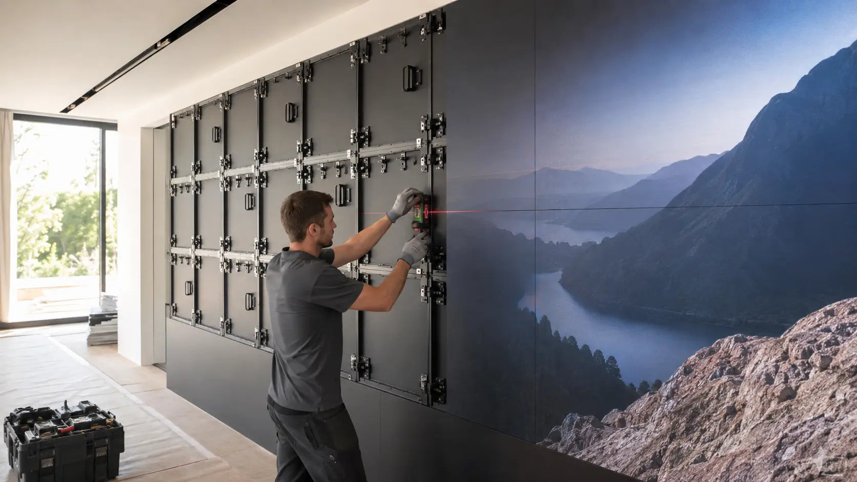
Before a cabinet goes up, verify the substrate and approved anchor locations. Then check the entire mounting plane with a long level or laser—not just the corners.
A small framing error can become a visible seam, a stepped cabinet, or hours of unnecessary adjustment later.
For a recessed installation, confirm the finished opening only after accounting for every finish layer: framing, sheathing, drywall, tile, wood panels, trim, and any reveal around the display.
For stone or other nonporous substrates, we encourage using a qualified local general contractor who can ensure the fit and finish needed.
4. Power Must Be Designed, Not Assumed
Next is power. Your job-specific drawing will list the proper power requirements for the screen.
The final circuit design includes multiple factors, including the actual display load, cabinet count, controller package, and local electrical code. Do not assume one ordinary outlet is enough, and do not bury extension cords or improvised power strips behind the wall.
A licensed electrician can confirm the required circuits, breaker capacity, outlet locations, grounding, surge protection, and any specified power sequencing or backup protection. Label every circuit before the cabinets arrive.
The goal is simple: correct power in the correct location, with nothing inaccessible once the display is installed.
5. Plan the Signal Path and Equipment Location
Identify the final location for every required component. This includes the video-processing unit, A V processor, network connection, home-automation interface and audio-system integration.
Every signal and data run should have a defined origin, destination, cable type and service path, with practical access for service work or future upgrades.
Depending on the selected processor and its location, Cat six may carry the longer data runs to the display. When the video processor and A V components share the rack, keep the local H D M I connection to three feet or less. For an approved system, an optical data connection may dramatically reduce the total number of cables required for the installation.
Provide conduit or another replaceable pathway wherever practical. Use a pathway sized for the approved cable package, with accessible endpoints and gentle bends that allow future replacement.
Technology changes. Cutting open a finished wall to replace one cable is an expensive way to learn that lesson. Label both ends and include enough service length to make final connections without pulling against a cabinet or connector.
6. Heat, Moisture and Service Access
Follow the project requirements for ventilation and operating temperature. Do not create a sealed heat pocket behind the cabinets, and do not aim an air-conditioning supply directly at the electronics where condensation could become a problem.
Front-serviceable modules make maintenance far easier, but the processor, power distribution, cabling and any rear components still need an intentional access plan. Make sure the back of the unit can be accessed easily.
7. Prepare for Delivery and Staging
Before delivery day, measure the entire route from the truck to the installation area: gates, stairs, elevators, doorways, turns and floor protection.
Clear a dry, climate-controlled staging area where every carton can remain upright, organized and protected.
When the shipment arrives, photograph the pallets and cartons before moving them. Record visible damage, verify the shipment against the packing list and organize the cabinets and components by installation sequence.
Do not discard packaging until the wall is installed, tested and accepted.
8. Final Go/No-Go Check
Before installation starts, confirm the final drawing, structural mounting plane, power, signal paths and protected staging area.
If one of those is not ready, stop and correct it before the first cabinet goes on the wall. That pause may cost an hour. Skipping it can cost days.
Next lesson: delivery inspection, opening the crates, inventorying every component and organizing the installation in the correct order.
Next lesson: delivery inspection and unboxing, followed by wall preparation, power and mounting plane; cabinet alignment; module placement and seam correction; processor setup; calibration and color; owner controls, maintenance and front service.